Homework 6A
Reminder!
The intent of many assignments/problems is to develop your experience and critical thinking skills, which often is the result of making mistakes and struggling to understand and correct them. The goal is not just submission of a correct solution — we already have solutions to the problems.
The time and work you invest is what has value. Consequently, use of A.I. tools is strictly forbidden on all aspects of this assignment.
Part 1
Conversion to RISC-V Machine Code
Convert each of these to machine code. Show work and the contents of all fields. Show the final result in 8-digit hexadecimal (like 0xABCD1234) with a box around it.
1. xor t0, t3, t6
2. lw t2, -4(sp)
3. andi t5, t6, 4
Conversion from RISC-V Machine Code to Assembly Language
Convert each of these RISC-V instructions to symbolic assembly language. Use register names (t0, etc.) rather than numbers or the generic names (don’t use 5 or x5). Write signed numeric values in decimal. Again, it may help to clearly show your final answer.
4. 0xFFD28F23
5. 0x003ECA37
6. 0xFEA2DCE3
Hints
Review Figure B.1 (first figure in Appendix B). Notice that all the instruction formats have field (part) in common. That part can be used to determine the instruction’s format.
- Once the format is known, other parts and values can be identified.
-
immvalues are signed and could be negative! - Some
immvalues are split up into parts in unusual orders and have to be re-assembled. Suchimmvalues may have “unspecified” bits that should be assumed to be 0.
Part 2: Assembly Language Programming
General
As is often the case, this includes both some runnable code that will be unit tested and content in questions.md that need to be completed.
Repository
Create a repository for your assignment via: link
Writing Assembly Language
Hints
Assembly language is tedious an error prone. It is always best to:
- When possible, like with
multiply, write and test the code in a programming language that you know. This will help you identify the concepts and critical logic. Assembly language is much easier if you already have correct logic. At the very least you should always have pseudo-code describing your approach. - Once you have an algorithm or pseudocode, make a new copy to add annotations (comments) to that will help you convert it to assembly language. Use concepts from assembly language, like replacing variables with register names. For example, replace
sumwitht2and leave comments that clearly show that every placet2is used it represents the sum. - You’ll need labels for loops and if/else statements. Add in comments indicating where you may need to use labels and what the label will be. Labels are like variable names — they should be descriptive and, although they can be used multiple places, they can only be declared in one place.
- On individual lines add comments describing instructions that you may need to use to accomplish comparable work in assembly language.
-
Use Indentation: It’s a lot easier to read and follow code that uses indentation in the same way as a high-level language program. Increase indentation on the bodies/statements of loops,
if-statements, etc. - If you attempt to run the simulator and it doesn’t start, that usually means there is a syntax error in your assembly language. Look at the
Terminaltab (and, more specifically theVenus Terminal) for errors. - When you encounter problems it may be beneficial to use breakpoints and the debugger to step through test cases. Carefully inspect the contents of registers to confirm values are behaving as you’d expect.
Running and Debugging RISC-V
Demo: The Completed Work
1. Delay function: delay(int ms)
Register Conventions!
This function is a “callee”. You should either: a) only use the registers that are allowed to be changed by a callee (nearly everything but sp and s registers) or b) use the stack to save the old values of any other registers and restore them before returning.
Refer to the section on function calls (6.3.7 and, especially, the sections on the stack and preserved registers).
One of the most common places where assembly language is still handwritten is where precise timing is necessary, especially in embedded systems. For example, many types of digital sensors require precise timing for communications. A delay method may be needed to ensure a delay for a required amount of time between changing a signal. We won’t need timing that is that precise, but being able to do some basic timing is beneficial.
Often such timing depends on a precise understanding of how much time is taken by individual instructions and then constructing a piece of code that runs enough instructions to consume the required amount of time. However, we’re currently working in a simulator, where the timing isn’t very precise. Depending on the specific machine running our Codespace, each instruction in the simulator will typically take between 0.25ms and 2ms (on average).
We will us an empirical approach to tuning our timing for a delay(int ms) function. The input parameter (a0) will indicate the number of milliseconds of delay that are required. You may assume it will always be greater than 10. Your approach should be accurate within about 10% of the requested value.
- Open
delay.sand start constructing your approach under the assumption that each instruction takes 1ms.- You may only use integer operations, but you may use
mulanddivif needed.
- You may only use integer operations, but you may use
- Try to identify a way to run sufficient instructions to account for the delay described by
a0. (Total code should only be about 5-25 lines). - Run the driver, which will run your code on four test cases. Note that it does short tests and longer tests. It’s hard to accurately measure short periods of time. Use a stopwatch to try to measure the accuracy of a long delay, like a 2 minute delay (you may have an stopwatch app on your phone. For example, the iOS clock app includes a stopwatch, or via google). Based on the measured value, calculate a correction factor and update your code to make this correction.
- Repeatedly adjust your timing approach until you have a method that is typically with 10% accuracy for 60s and 120s. You can adjust the test cases on line 3 of
delay_driver.s(add or remove tests) to focus any debugging or testing.
2. Multiply function: multiply(unsigned multiplicand, unsigned multiplier)
Requirements!
Our final processor will not have a mul instruction. For credit you must implement the basic algorithm described below with only integer operations and without using mul or div !
Register Conventions!
This function is a “callee”. You should either: a) only use the registers that are allowed to be changed by a callee (nearly everything but sp and s registers) or b) use the stack to save the old values of any other registers and restore them before returning.
Refer to the section on function calls (6.3.7 and, especially, the sections on the stack and preserved registers).
Multiply should multiply the contents of a0 and a1 using a fast, shift-based multiplication algorithm:
sum = 0
while(multiplier > 0) {
  if(lowest bit of multiplier is a 1) {
    sum = sum + multiplicand
  }
  multiplier = multiplier >> 1
  multiplicand = multiplicand << 1
}
multiply_driver.s contains many test cases, which are listed one per line from line 6 to line 230. As before, you are welcome to adjust the test cases to focus debugging (add more/differnt tests, comment out tests, etc.)
3. Spinner function: spinner(int spins, int segment_time_ms, int digit)
Register Conventions!
This function is both a “callee” and a “caller”. You will need to take special precautions! Refer to the section on function calls (6.3.7 and, especially, the sections on the stack and preserved registers).
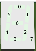
If you recall, Homework 4B included a “spinner” element that showed the progress through an individual wash phase. We can also implement this sort of behavior via code. Appropriate behavior will require using your delay method as well as a provided method to access the display called set_segments(unsigned digit, unsigned value), which behaves as:
# Parameters
#   a0 is the 7-segment to change (0 is rightmost / least significant digit on the display)
#   a1 is the value to set (low 8 bits)
# Return value
#   none / undefined
# Side effects
#   all non-caller-saves registers may be changed
set_segments:
The a parameter has the on/off values of individual bits:
Complete an implementation of spinner() that behaves as described:
spinner:
# Parameters
#    a0 the number of "spins" (complete rotations, clockwise around LEDs of a digit)
#    a1  the time to delay with each segment on (in milliseconds)
#    a2  the digit to use (0 is rightmost / least significant digit)
# Return value
#    a0  none / undefined
# Side effects
#    Delay for approximately 6*spins*segment_time milliseconds and displaying a pattern on the designated digit
- It should always start with segment
0on. - A full spin ends with segment 5 (total of 6 steps).
- Each segment should be lit for the given delay.
- All segments should be turned off at the end.
4. Questions: questions.md
As in past assignments, complete the questions in questions.md
Submission
You will need to submit your assignment via Gradescope. There will be two dropboxes:
Part 1, 1-6
As in the past, you need to indicate where your work is for each individual problem.
Part 2, 1-3
As with Homework 4A, you will need to commit and push work to GitHub and then go to Gradescope to “pull” the work over.
- Submission Link: Gradescope