Studio 3B
Overview / Reminder
- Work in small groups
- Studios are a time to explore the material and refine your understanding.
- You should NOT “divide and conquer” to complete all of the studio. The time is meant for improving your understanding.
- You should ensure that everyone in your group contributes to and benefits from the work.
Artifacts for this studio
Include an answer to questions in the numbered sections in your submission. Include the relevant section number for each answer, like 1.1.
Chapter 3: Synchronous Logic
State Representations
Binary Counting vs. One Hot Encoding
Two of the extremes in state encoding are binary encoding (counting states from 0 to $n$) and the one-hot encoding. Consider a Moore-style machine with 10 states, a single input named input, and a single output named output:
- How many bits, $k$, are needed for a binary state encoding?
- Assume that the
output’s value depends on being in one of three specific states, either state 0, state 6, or state 9. A pseudo-code form ofoutput = in_state_0 + in_state_6 + in_state_9. Provide the complete equation for the output in terms of the state bits, $S_{k-1} \cdots S_0$. - How many bits, $l$, are needed for a one-hot state encoding?
- Provide the complete equation for the
outputin terms of the state bits, $S_{l-1} \cdots S_0$.
Stating the Abstract
Assume you have more generic problem with $n$ states and that the output or next state equations will depend on being able to identify or detect each of the $n$ states somehow (that is, you’ll need some circuit to determine if you’re in state 0, and another to determine if you’re in state 1, etc. This is very comparable to the equations you created in the prior part).
Based on how both flip-flops are constructed and how states are detected:
- Come up with formulas that describe the minimum number of basic logic gates needed for each encoding. That is, count the basic logic gates (like
AND,OR,NOR,NAND, but you can ignore invertors).- How many 2-input gates are requires for a single D flip-flop? Assume we’re using the basic flip-flop model covered in lecture that is composed of D-Latches, which were made from SR-Latches, which were made from
NORgates (hint: See problems in part 2 below for diagram). - Below is a table that can help compare the total number of gates that may be required for each type of encoding. Again, assume there needs to be some way to recognize (decode) all of the $n$ possible stateis. Complete the table with each box describing the number of gates in terms of the number of states, $n$, for the encoding ($n$ is the number of states, not number of state bits!). For example, use summaries in terms of $n$ like: “$log_2(n) \times$ 2-input gates” or $n \times n$-input gates”, etc.:
Encoding gates for storage gates for decoding Total gates (storage+encoding) Binary One-Hot - How many 2-input gates are requires for a single D flip-flop? Assume we’re using the basic flip-flop model covered in lecture that is composed of D-Latches, which were made from SR-Latches, which were made from
- Total space taken to construct circuits will largely depend on the number and the width (number of inputs) of gates being used. Try to estimate how the space needed to construct the circuits will differ. For example, you may start with the assumption that a $j$-input
ANDtakes $\frac{j}{2}$ times more space than a 2-inputANDand express the total space taken in terms equivalent to the total space that would be taken by 2-input gates. - Based on the prior work, provide rough guidance for when someone wants to minimize space for:
- When one may prefer binary encoding.
- When binary and one-hot encoding may be nearly identical (using these assumptions and models of gates/flip-flops).
- When one may prefer one-hot encoding.
- There’s often a tradeoff between efficiency, and the time and effort required to design, test, debug, and verify a systems. When or why may an encoding style be easier for design/test/debugging?
Flip-Flop Timing: Empirical Measurements
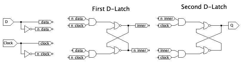
In class we constructed an SR Latch from cross-coupled NOR gates. Then stacked some AND gates in front of the SR Latch to make the D-Latch. We then used two D Latches in sequence to create a D Flip-Flop, which has much more precise control of when data is captured. The two D Latches use opposite phases of the clock: The first D-Latch is transparent when the clock is low and captures the data value when the clock level is high. The second D-Latch is the opposite: it is transparent when the clock is high and captures the value when the clock is low.
Construct the following D-Flip-Flop Model in JLS:
Test Your Flop Flop
- Estimate the propagation delay by considering the path from D through to Q, including one potential “loop” for each latch. Round that up to the nearest 100 and consider it to be a safe value for the clock cycle.
- Test your work. Confirm that you can store both a
1and a0.
Describe any unusual behavior at the start of the simulation.
There are multiple facets of timing that are important in synchronous circuits, including the maximum clock speed and ensuring that D Flip Flops behave stably.
Estimating and Empirically Testing Parameters
Based on inspection of the circuit, find $t_{cq}$, The propagation delay from a rising edge on Clock until a change in Q.
Empirically Testing $t_{cq}$
Test your estimate:
- Create a test case that initializes the flip flop in the first 500 units of time. For example, include updates in both
DandClockthat set the output to a known value. - After your setup phase, use a
? until 500clause on bothDandClockto wait until 500 units of time. For example, the clock may: start at 0, go to 100, go back to 0, and then0 until 500to wait (at value 0) until $t=500$. - Construct an experiment starting at $t=500$ to change the value of the flip flop. Confirm your $t_{cq}$ value.
- Update your experiment: If it set
Qto a 1 after time 500, change it to set it to a 0. - Are the $t_{cq}$ times for changing-to-1 and changing-to-0 the same or not? Explain the behavior and timing.
Empirically Finding Setup Times & Influences
Timing and Testing
Careful use of for and until blocks can allow you to precisely and easily test both setup times (using until $t_{setup}$ before the clock) and hold times (using until with the time of the rising edge and for with the $t_{hold}$)
It may help to sketch out timing signals on a graph for the following problems
A flip-flop’s setup time ($t_{setup}$) is the amount of time the D value must be stable before a clock cycle to reliably store a value. Update your previous test cases to:
- Again, set
Qto a know value and wait until 500 units of time. - Pick a time for a rising edge of the clock, like $t=700$.
- Have
Dchange values near the rising edge of the clock (and be stable for quite a while - you may want to use aforclause, like1 for 100to hold the signal). Experiment to identify how much time may be needed to reliably store the correct value. For example, change the point whenDchanges to be closer and closer to the clock edge until the value ofDis no longer successfully stored. - As before, update your experiment: if the stored value was a 1, update it to store a 0 and see if the $t_{setup}$ is consistent.
- Explain your results. Based on your testing what does $t_{setup}$ appear to be for this flip-flop model and why does this make sense?
Empirically Finding HOLD Times & Influences
A flip-flop’s hold time ($t_{hold}$) is the amount of time the D value must be stable after a clock cycle to reliably store a value. Do a variation on the prior part to determine the hold time required for your flip-flop model.
Aperture Time
The aperture time is the total amount of time the D value must be stable. What is the default aperture time for this flip-flop in JLS?
Caution!
JLS simulates perfect conditions of ideal logic. It provides a useful model for understanding some of the factors in circuit timing, but it does not perfectly explain specific implenetations.
Wrapping Up
If you have extra time and didn’t finish Studio 3A, spend any remaining time completing it.
Submission / End-of-class
Submit a copy of the questions with everyone’s name at the top (at least one person should submit it, but it’s ok if everyone does).
Submission Link: Canvas