Studio 3A
Overview
Studio sessions must be done in small groups of 2-4 people. The group work is an important part of the studio experience. You are not required to work with specific students and may adjust groups next week or when we move to a new room. We expect you to be be respectful and professional in your interactions with your peers.
You should ensure that everyone in your group contributes to and benefits from the work.
Artifacts for this studio
Include an answer to questions in the numbered sections in your submission. Include the relevant section number for each answer, like 1.1.
Chapter 3: Sequential Logic Part 1
Latches & Flip-Flops
Description
Briefly describe the difference between a latch and a flip-flop.
The Edge edge
Why is it important to have an edge-triggered flip-flop and what is required for its construction?
Real D Flip-Flops
Examine the data sheet for the 74175, D-Type Flip-Flop chip: Data Sheet.
How many bits of memory does the chip contain?
Explain what the Master Reset does.
JLS D flip-flop model
Open JLS, create a new circuit, and examine the D flip-flop provided (Remember that Flip-Flops are edge triggered! Use the positive edge triggered flip-flop by picking the Pos-Trig Trigger, which should be the default setting).
How is the JLS D Flip-Flop different than the 74175?
Use the following to control the D Flip-Flop (Input is the data to store).
Input
    0 for 200
    1 for 200
    0
end

Clock
    0 for 60
    1 for 60
    0 for 60
    1 for 60
    0 for 60
    1 for 60
    0
end
Explain the Output of the flip-flop for those inputs.
JLS Registers: Multi-bit flip-flops
A group of flip-flops that collectively store a multi-bit number is referred to as a register. You may have noticed that JLS calls the flip-flop part a register. Download and examine this JLS file which includes a 4-bit register and a signal generator: studio_3a_register.jls.
Review the signals being used and explain why some values are being shown on the output (current) and others are not.
Replace the register with an 8-bit register. Update the signal generator with test cases that confirm that 8-bit numbers are able to be stored.
State Machines
Stating it
Give a definition of a state machine in your words as though you are explaining it to someone without a technical background. If possible, give relatable examples of state machines and describe what the “state” actually refers to.
Someone in the last row of the room thought they heard Prof. Siever mumble “… memory, like flip-flops, is essential for building state machines”. Explain if you think this was what was actually said and what might have been meant.
Refer to the first paragraph of Wikipedia’s article on Finite-state machines. Does it include anything that may imply a need for memory?**
Ups and Downs of Diagrams
State diagrams are a tool for both:
- documenting the details of state machine behavior and, more importantly,
- visually communicating with others about how state machines should behave.
Consider the following diagram for a simple elevator that goes between two floors (first floor and second floor) and has:
- Four inputs:
- A button that requests the elevator go up (called
up) - A button that requests the elevator go down (
down) - A sensor that detects when the elevator is at the top (
at2, indicating it is at the second floor) - A sensor that detects when the elevator is at the bottom (
at1)
- A button that requests the elevator go up (called
- Four outputs:
-
first_lightindicates it’s at the first floor -
second_lightindicates it’s at the second floor -
move_upcontrols both the motor that moves the elevator up and a light showing that it’s going up -
move_downcontrols both the motor that moves the elevator down and a light showing that it’s going down
-
Consider the following state diagram:
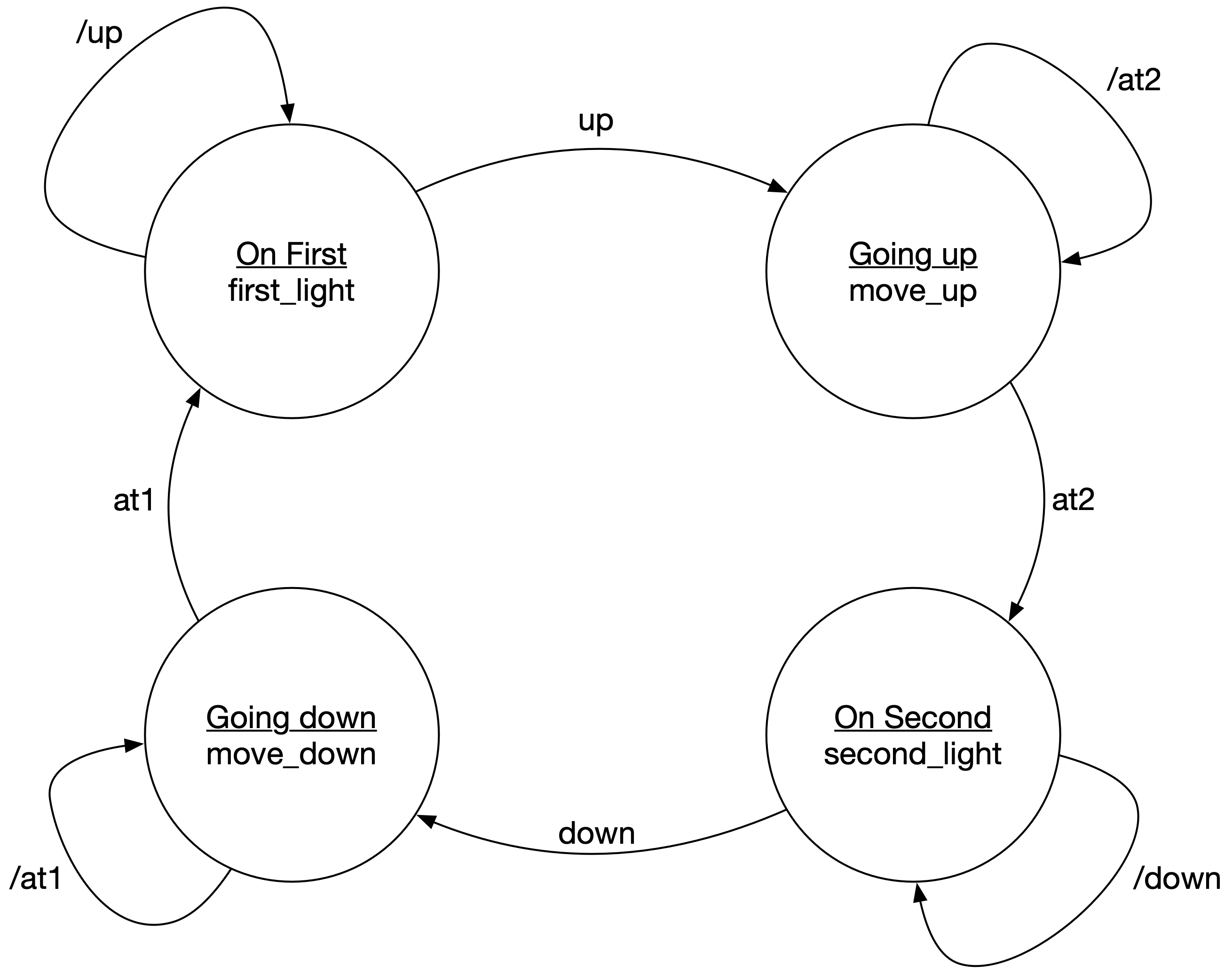
Does this appear to be a correct description of the elevator’s expected behavior? If not, explain errors suggest how to fix it.
Describe the overall sequence that would happen if the elevator starts on the first floor and a person wants to operate it to travel to the second floor.
If implemented exactly as described, what would happen if someone presses the Down button while the elevator is going up?
Assume the elevator takes 2 minutes to travel between floors. What could happen if the clock cycle used is 10 seconds? What about if it’s 240 seconds? How would these values impact passengers and the motors being used?
State Representation
What is the minimum number of bits that must be used for the elevator? Explain your reasoning.
Circuits
Circuits for finite state machines can be organized in two styles, the Moore style and the Mealy style. Moore style machines have outputs that depend only on the state and can be represented as:

The next state logic and output logic are just combinational logic and can be represented with a table and then converted to a corresponding digital logic circuit using techniques covered previously. The box in the center, which is driven by a clock, is a register that stores the state.
The next state logic and output logic can be represented with tables. Describe the columns included in these tables and what they mean.
Implementation
Download and open studio_3a_elevator.jls. Notice that it makes extensive use of named wires to help organize the diagram. It also uses a decoder for state.
Open this google doc worksheet and either copy its contents to your doc or create a copy of the Google doc to work from. Then:
- Complete the State Table based on the JLS circuit (what state to state bit encodings represent)
- Complete the Output Table (note that you can use the named wires that identify the state — they are already “decoded” for you)
- Complete the Output Equations
- Complete the Next State Table
- Complete the Next State Equations for the output state bits (
ns1andns0). - In the JLS file, complete the connections to the output pins using your output equations
- In the JLS file, complete the circuits for the combinational logic for
ns0andns1based on your equations. - Identify the maximum possible clock cycle.
- Create a test case that moves the elevator from first floor to second and then back to first.
Submission / End-of-class
Submit a copy of the questions with everyone’s name at the top (at least one person should submit it, but it’s ok if everyone does).
Submission Link: Canvas