Studio 7A
Names
Open questions.md and list the names of everyone in your group.
Single Cycle Data path & Control Basics
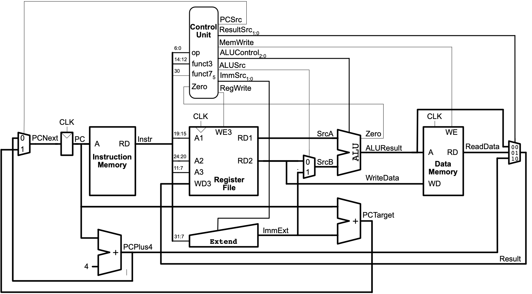
Consider the single-cycle CPU model covered in reading and lecture:
addi
Assume that an addi t0, t1, 12 instruction is being run. Describe the values or meaning of all signals in the above diagram that are needed for this instruction to behave correctly. If a particular control signal isn’t relevant, indicate it’s value with “Don’t care”. (Answer in questions.md)
The Extend unit does Sign Extension on some mixed-up version of its input based on the ImmSrc control:
ImmSrc Value |
Output |
|---|---|
00 |
Sign Extend input[31:20]
|
01 |
Sign Extend {input[31:25], input[11:7]}
|
10 |
Sign Extend {input[7], input[30:25], input[11:8], 1'b0}
|
11 |
Sign Extend {instr[19:12], instr[20], instr[30:21], 1'b0}
|
subi is missing!?!?
Prior programs needed to add and subtract from the sp, but there isn’t a subi instruction. Explain how/why the Extend unit provides vital support for cases like this. (Answer in questions.md)
call / jal
The pseudo-instruction call can be used to call a function. In our simple cases it always translates into a jal ra label (and many examples simply used jal label). Review the meaning/behavior (also referred to as its “semantics”) of jal and its format in Figure B.1 and Table B.1. The “Operation” column gives a precise description of how the instruction impacts the machine state.
Describe the values or meaning of all signals in the above diagram that are needed for a jal main, where main has the value 0x100, to behave correctly. If a particular control signal isn’t relevant, indicate it’s value with “Don’t care”. (Answer in questions.md)
jal’s JTA
j is a pseudo-instruction that translates into a jal. For example, j loop would really be represented as jal zero loop.
The “Jump Target Address” used in the jal instruction is considered PC Relative. Consider the following code snippet:
// This is point X

loop:
    ...
// This is point Y

   ...
   j loop
Describe how the binary encoding of the jal instruction here would change if 1) Instructions are added at point X (but not Y) and 2) If instructions are added at point Y (but not X). That is, how would changing these locations impact the value used for j loop (jal zero loop) machine language shown on the last line? (Answer in questions.md)
Alternatives
An alternative to “PC Relative” is Absolute addresses. If the jal used absolute addressing, how would the machine language for jal change for the two cases: 1) Instructions are added at point X (but not Y) and 2) instructions are added at point Y (but not X).
Single Cycle Partial Implementation
The Edit riscvsingle.sv task can be used to edit a partial implementation of a single-cycle RISC-V processor.
Caution!
This is a moderately real-world example! It can seem a bit intimidating. It’ll be helpful if you try to develop a moderate understanding of it before you make any modifications. Work carefully/methodically.
The RISC-V model was developed in conjunction with the diagram shown above and all the elements in the diagram have some corresponding component in the Verilog.
Make a Map / Outline
Review the code and the diagram. Try to make a map or outline of how the parts fit together. Write up your initial summary in questions.md
Be specific
Consider the addi example from before. Try to identify how the specific modules in the riscvsingle.sv would be used in it’s execution. Again, summarize your findings in questions.md.
Identify any new Verilog ideas / syntax
Note that the authors are quite comfortable with Verilog. This model uses some “pro tricks” that you may not have thought of. Review the code and try to identify things that may be beneficial (keeping in mind that you will soon have to modify this code). Again, summarize your findings in questions.md.
xor
The provided implementation has partial, but incomplete support for xori. Try to identify where/how to update it to supports xori. (Hint: 1 line of code needs to be added)
Run the RISC-V xor Testbench to confirm your changes provide correct support for xor. The test bench should display "All tests passed" in the “Problems” tab if it passes all tests. If there are errors you may need to review the contents of the testbench’s tab in the “Terminal” pane (which is in the same area as the “Problems” pane).
You can use the Edit xor Testbench task to review the contents of the testbench. It’s just trying a few specific xor and xori instructions.
On Hardware
The Edit xor_driver_hardware.s task can be used to open a very very simple hardware driver. It will read in the 8 buttons on the keypad and xori them with 0x55 (you can change the 0x55 later). To program your board with the CPU model and code:
- Use
Convert xor_driver_hardware.s to ROMtask to convert the assembly language to machine code in a suitable format for the FPGA. Carefully look at the resulting file and try to ensure it only uses instructions supported by the CPU model. You need to re-run this task any time you change the .s file. - Use the
RISC-V+xor_driver_hardware.s bitstreamto convert the entire CPU model and program to a bitstream to program the FPGA.
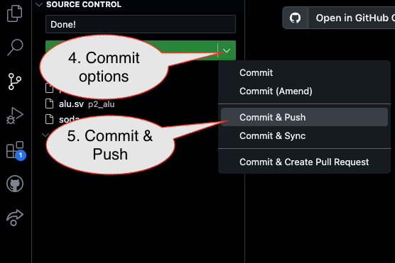
Submission / End-of-class: Commit And Push
1. First, be sure to commit and push files to GitHub (as shown in studio)
1.1
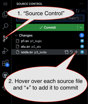
1.2
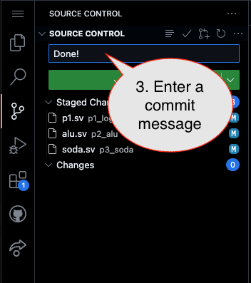
Caution!
Failure to type in a commit message will cause VSCode to open a window to enter the message (in the editor area) and the Source Control pane will appear to be stuck (a waiting animation) until you type in a message and close the message pane.
1.3
2. Then go to GitHub.com and confirm the updates are on GitHub
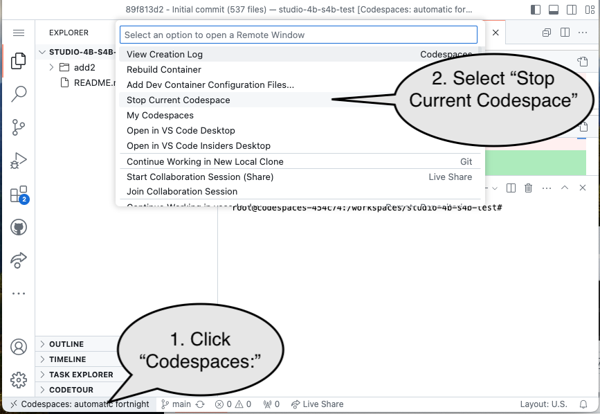
End of Studio: Stop the Codespace
Caution!
Be sure to “stop” your Codespace. You have approximately 60 hours of Codespace time per month. Codespaces often run for ~!5 minutes extra if tabs are just closed.