Studio 4B
Overview / Reminder
- Work in groups of 3!
Studio Setup
Follow the steps from Studio 4A! The assignment link is link
Names
Open questions.md and list the names of everyone in your group.
Fulladder: Again
Use task 2.1 to (again) complete a behavioral model of a full adder (you can use work from last studio).
Use task 2.2 to simulate / test your work.
Use task 2.3 to confirm your work via a testbench.
Use task 2.4 to complete question 2.4 in questions.md
Mapping to hardware
Your kits contain an iCE40 UP5k FPGA. Review the Data sheet for the iCE40 UP5K. In particular look at Figure 3.2, whcih describes the “PLBs” in the UP5K. Until now we’ve been using HDLs to depict circuits using digital logic schmatics, which don’t exactly correspond to how the FPGA will be used.
Use task 2.4 to see how our synthesis tools utilize the FPGA. Complete question 2.4 in the questions.md
Multi-bit addition
Use task 3.1 to complete a structural model of a 4-bit adder using 4 instances of your full adder.
Use task 3.2 to simulate your work
Use task 3.3 to verify your work via a testbench
Making it real
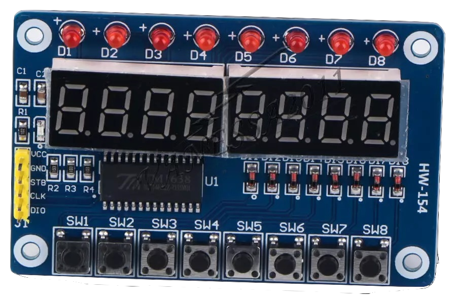
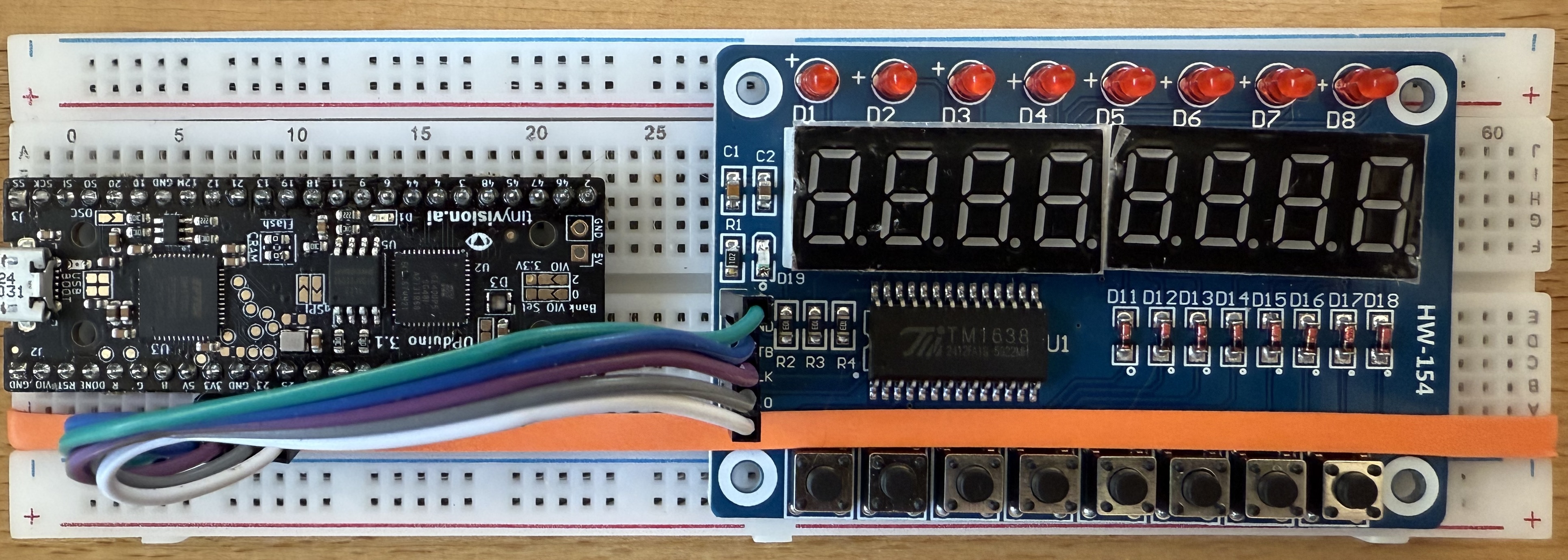
Your kits contain an LED & Key module that includes 8, 7-segment displays, 8 traditional LEDs, and 8 push buttons. The module is controlled by the TM1638 (which can be controlled by a state machine!).
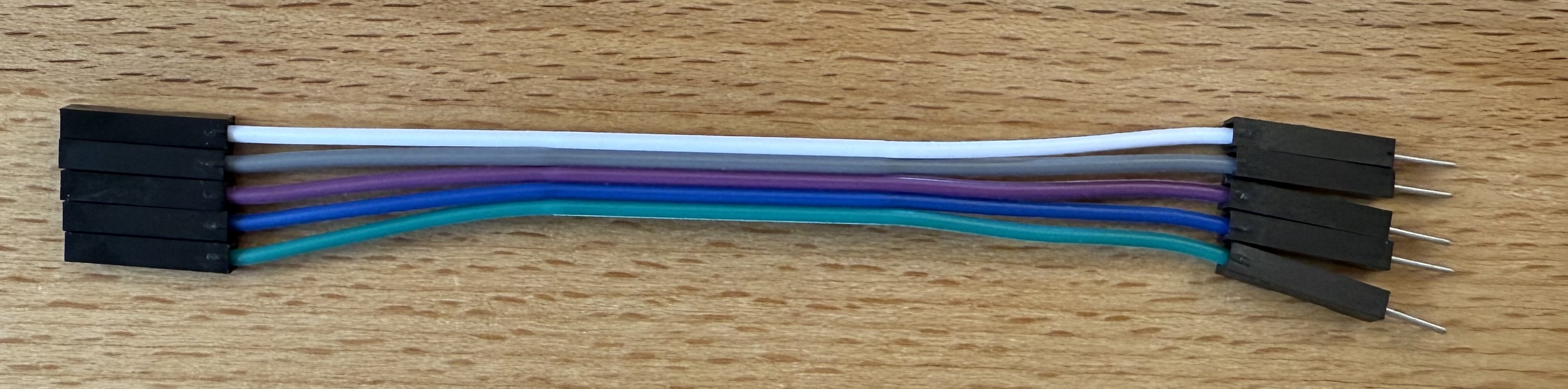
Your kit also comes with a male to female jumper wires that can connect your breadboard to the module. Tear off a group of 5 wires (no need to separate them into indivudal strands — it’ll be a little easier if they are connected together):
Use the cable to connect the UPduino to the board:
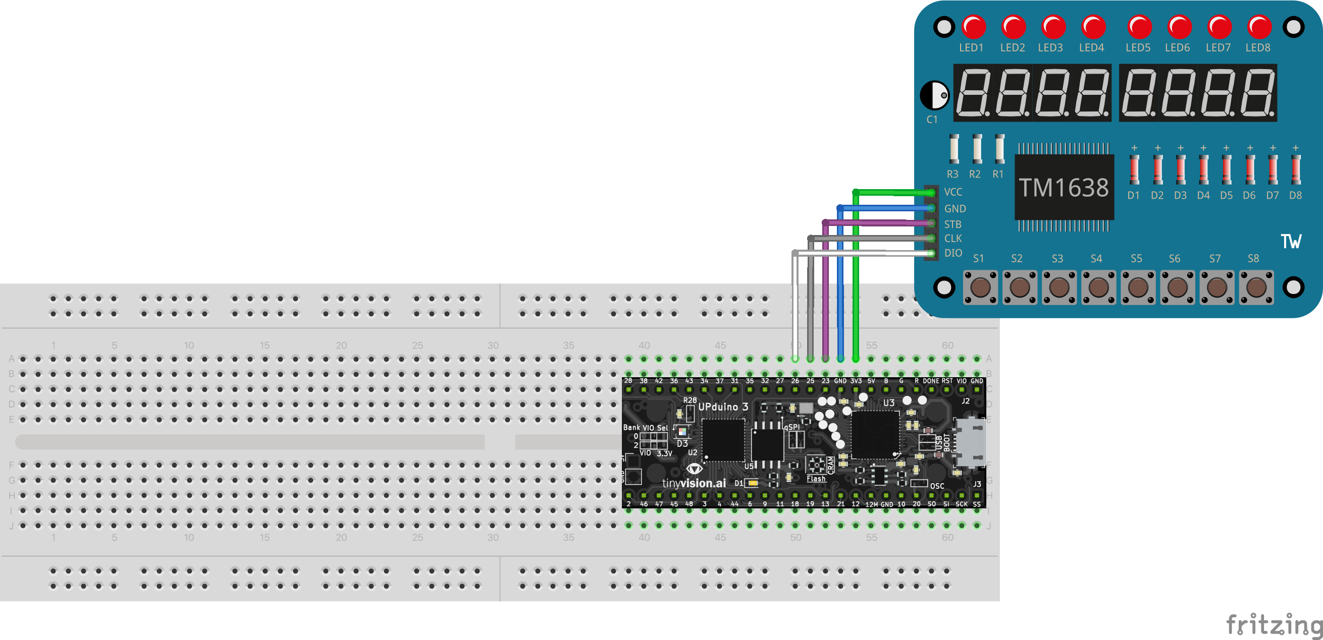
| UPduino Pin Number/Name | Board Pin Name |
|---|---|
| 3V3 | VCC |
| GND | GND |
| 23 | STB |
| 25 | CLK |
| 26 | DIO |
It should look about like below (the board has been rotated and a rubber band has been used to hold it to the breadboard):
Testing Connections
- Double check all wires.
- Connect the UPduino to your computer with the USB cable.
- Start the
FPGA Programmer Servertask. - Connect the the UPduino.
- Review the FPGA Programming page.
- Today’s Codespace contains a
ledandkey_test.binimage. Program it on the UPduino. If it works, the board should show the digits 7-0 and pressing each button should cause a corresponding LED to light up. Confirm that the board is connected correctly and works.
Testing your adder
Task 3.5 creates a bitstream file for your four-bit adder. If done correctly, the left four push buttons will control the left most digit. The right most four push buttons will control the middle digit. Each nibble will be added, using your four-bit adder, and the result will be displayed on the rightmost digit.
After generating the bitstream, upload it to your UPduino.
State Machines
statemachine.sv
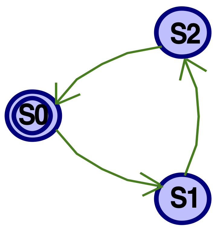
Complete code for a statemachine that implements the “Everythird” behavior covered in class.
Simulate
Use the simulator to confirm that it works as expected.
A Testbench
Use task 4.3 and 4.4 to complete a test bench to verify that it works correctly.
Verification: Complete code to verify your work
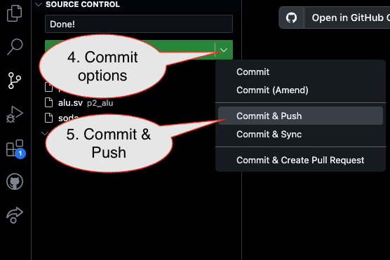
Submission / End-of-class: Commit And Push
1. First, be sure to commit and push files to GitHub (as shown in studio)
1.1
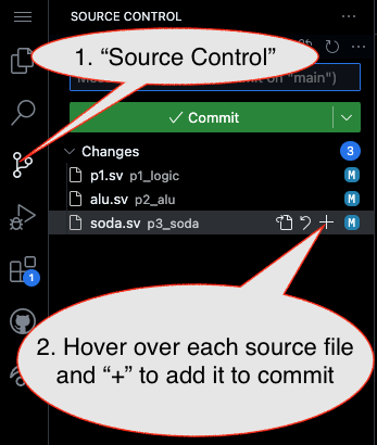
1.2
Caution!
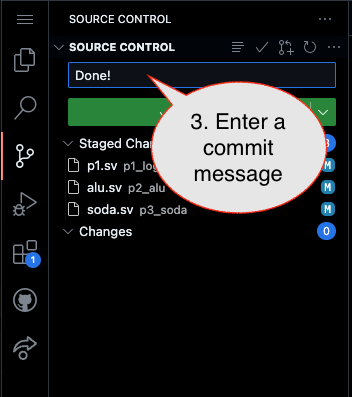
Failure to type in a commit message will cause VSCode to open a window to enter the message (in the editor area) and the Source Control pane will appear to be stuck (a waiting animation) until you type in a message and close the message pane.
1.3
2. Then go to GitHub.com and confirm the updates are on GitHub
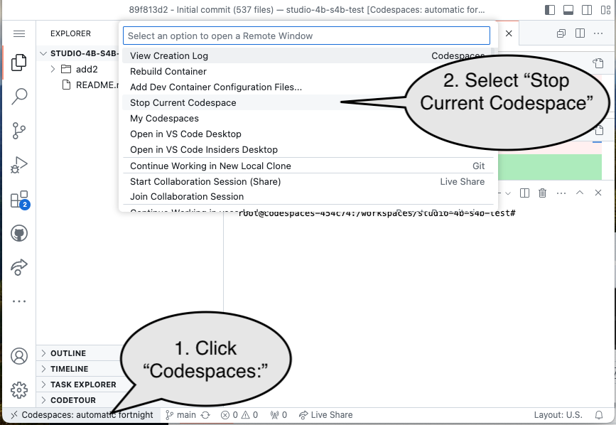
End of Studio: Stop the Codespace
Caution!
Be sure to “stop” your Codespace. You have approximately 60 hours of Codespace time per month. Codespaces often run for ~!5 minutes extra if tabs are just closed.