Homework 5A
Demos!
An in-person demo will be required for full credit. Pay careful attention to the details below to prepare for the in-person demo!
Repository
Create a repository for your assignment via: link
ALU Construction Concepts and Requirements
An Arithmetic Logic Unit is a fundamental part of CPUs. An ALU generally has three inputs and at least one output. Two inputs represent values to be combined by an operation and the third input describes how those values should be combined to produce the output.
A simplified version of the ALU from chapter 5 (Figure 5.18 b) is:

The behavior of this ALU can be described with the following table:
| ALUControl | Result |
|---|---|
| 000 | A+B |
| 001 | A-B |
| 010 |
A AND B (bitwise and) |
| 011 |
A OR B (bitwise or) |
| 100 | undefined |
| 101 | 1 if A<B (signed values), 0 otherwise (using the logic in the diagram) |
| 110 | undefined |
| 111 | undefined |
We will implement a slightly more capable version that supports:
| ALUControl | Result |
|---|---|
| 000 | A+B |
| 001 | A-B |
| 010 |
A AND B (bitwise and) |
| 011 |
A OR B (bitwise or) |
| 100 |
A XOR B (bitwise xor) |
| 101 | 1 if A<B (signed values), 0 otherwise (using the logic in the diagram) |
| 110 | Shift A left by B bits (logical shift) |
| 111 | Shift A right by B bits (logical shift) |
- A bitwise operation combines corresponding bits of multi-bit values. For example, if
AandBare two-bit numbers, the 0th bit of the bitwise AND would be from ANDing the 0th bits ofAwith the 0th bit ofB. The 1st bit of the bitwise AND would be from and-ing the 1st bits ofAandB, etc. - “Less than” can be determined by either (but not both) a negative result from
(a-b)or if(a-b)results in overflow. You can use the exact logic shown in the diagram. - The ZeroExt unit shown in the diagram is “extending zeros”. Theless-than operation produces a 1 or a 0 result. Only the least significant bit is used and the remaining bits are 0. For example, the result of the less-than operation on a 32-bit ALU will be either
0x00000001or0x00000000(the0xnotation indicates base-16, like32'h00000001).
Our ALU module and interface ports will be defined with:
module alu
#(parameter SIZE = 32)
(
    input logic [SIZE-1:0] a,
    input logic [SIZE-1:0] b,
    input logic [2:0] control,
    output logic [SIZE-1:0] result,
    output logic zero
);

 ...
The SIZE parameter will allow the ALU to be used with any word size desired. This assignment will use both 32-bit words (the default and eventual goal for our RISC-V CPU) and 4-bit words.
Zero Flag
Another improvement to the diagram above is the addition of a “zero flag” output, named zero. The zero flag is an output that is a 1 if (and only if) the result from the ALU is 0.
Why?
Checking for a zero result is a common and really useful operation. For example, the expression if(a==b) can also be thought of as if(a-b==0). Our ALU will support subtraction, which can be used with the zero flag to support checking for both equality (==) and inequality (!=).
ALU Development
- Use the
Edit alu.svtask to edit your ALU design. -
You can use the
Simulate alu.svtask to simulate your work.Hints
- Develop Incrementally! Do one or two operations and use the simulator to review your work/progress.
- Verilog’s
if/elseorcasestatements (both described in chapter 4) are great choices for most of what ALUs need to do. - Bit subscripting (
[]) and bit swizzling (book examples 4.12 in section 4.2.9) are useful here! - Bit swizzeling techniques use the concatenation/replication operators,
{and}. The{ ... }can contain a comma-separated list of values (constants or signals). Putting a constant integer in front of a group, like{3{1'b0}}will replicate the contents. It can be an integer expression based on a parameter (as long as the result is a non-negative constant number), like{(SIZE){1'b0}}, which would be a value withSIZEbits of0.
-
Use the
alu32 testbenchtask to test your 32-bit ALU on some randomly generated values and randomly selected operations.Common Warnings
If you use an
always_combblock, running testbenches may trigger a warning that sayssorry: constant selects in always_* processes are not currently supported (all bits will be included)..A “constant select” is any expression that uses a constant to select bits of a larger value, like the
[2:1]inmode[2:1]. The warning refers to how the Verilog simulator, iverilog, identifies when to perform thealways_comband what things it’s sensitive to (the effective sensitivity list). In an ideal world, it would only use the values that are absolutely essential and ignore any bits that aren’t necessary for thealways_comb. For example, ifmode[2:1]were the only reference tomodein analways_comb, it shouldn’t update anything if the only value that changes ismode[0]. The message indicates that the simulator isn’t currently that selective and will recompute thealways_combblock if any bits in any relevant value change (not just the subset of bits that were selected). In the majority of cases this means the simulator is doing a little additional work, but the extra work doesn’t usually have an impact on the results. That is, this is really a warning about the simulator behavior’s precision and can usually be ignored. - Use the
alu4 testbenchtask to test your 4-bit ALU on an exhaustive set of values and operations (all 211 combinations).
Hardware 1: Basic ALU Calculations
The alu bitstream task can be used to program your FPGA in a way that will allow you to test your ALU in hardware. (Don’t forget that you need to be running the FPGA Image Server task). The hardware I/O is configured as follows:
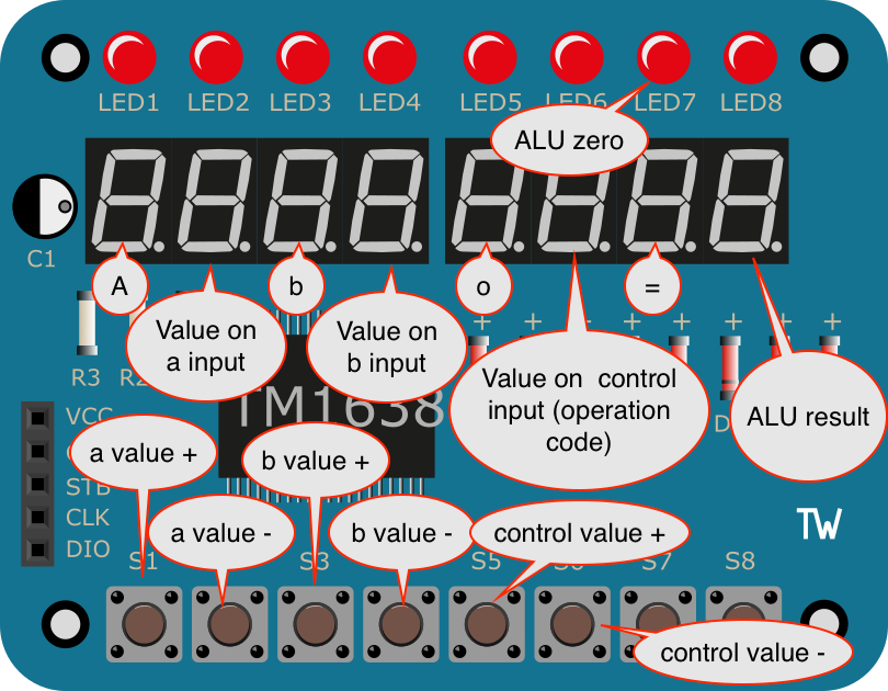
Buttons can be used to select the 4-bit input values to the ALU and the operation code (ALU control) being applied. Both the result and the zero flag will be displayed.
A demo:
Hardware 2: An ALU Calculator with Memory
- Use the
Edit register_file.svtask to view (not edit) the provided register file, which uses parameters for both word size and number of registers. Review the default values that are placed in registers. - The
calculator_top.svfile, which you will examine in a bit, configures a 4-bit ALU and 16, 4-bit registers. The registers allow you to store values and use them with the ALU. - The
calculator bitstreamtask can be used to program your FPGA in a way that will allow you to test your ALU in hardware. It connects your ALU to the register file as follows to create a primitive calculator with memory: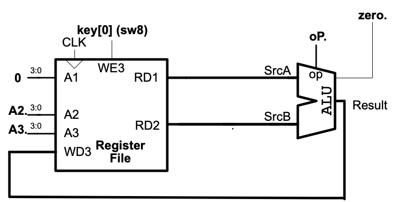
-
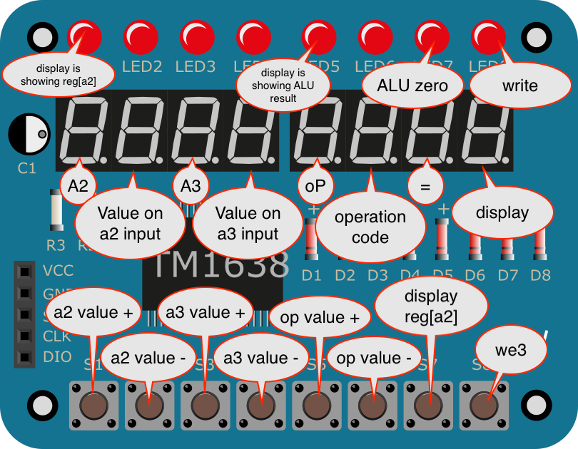
The LED & Key module is configured as follows:
Demo Prep
The demo will ask you to find ways to do some simple computations using the ALU Calculator and may ask that you use specific operations. You may want to think about the shortest/easiest way to do certain operations. Some examples:
- How can you get the value 15 in register 4?
- How can you get the value 5 in register 6?
- How can you get the value 5 in register 4? (Easier or harder than in register 6?)
- How can you add 2+4 and store the result in register 2?
- What’s the easiest way to set register 0 to 0?
- What’s the easiest way to shift 1 left 3?
- What’s the easiest way to do a bitwise AND of
'h3and'hA
Questions
Answer the questions in the question.md in the designated places (remove / replace the TODO lines). There are questions that involve the final two tasks.
Submission
The assignment will be submitted via GitHub and Gradescope.
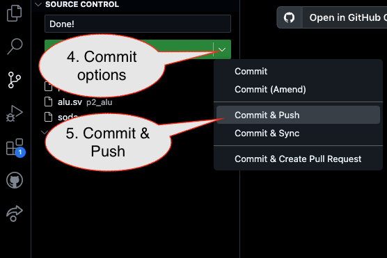
1. First, be sure to commit and push files to GitHub (as shown in studio)
1.1
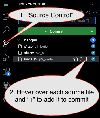
1.2
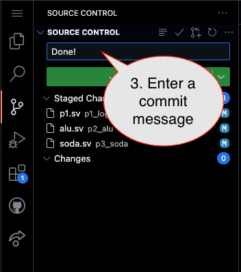
1.3
2. Then go to GitHub.com and confirm the updates are on GitHub
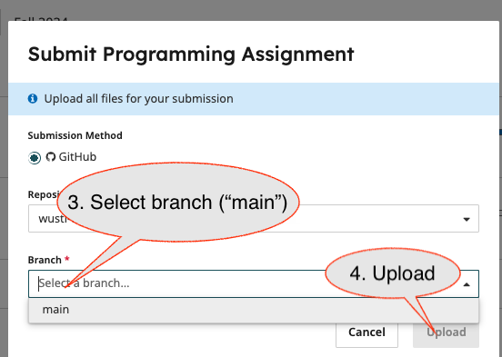
3. Finally (after confirming updates are on GitHub), go to the assignment in Gradescope and import it from GitHub:
3.1
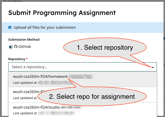
3.2
- Submission Link: Gradescope